
Moggy's Notes
3dz Linkpoints and "Paste-on" files
(1) The Basics
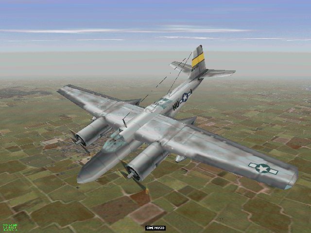
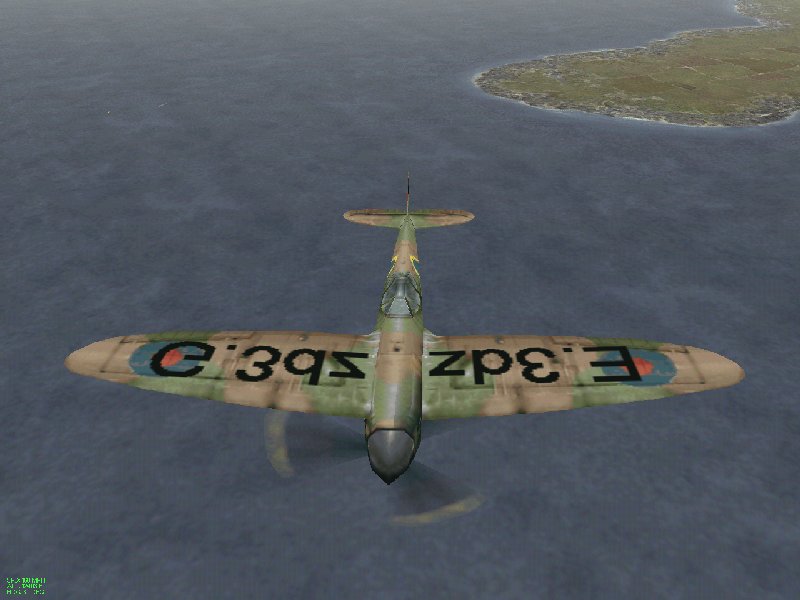
The ultimate development of the EAW 3dz model is found in the four engine bombers. These aircraft are composed of six different 3dz files, pasted together by hardpoints analogous to the hardpoints that place visible external ordnance.
The six files are:
P????F.3dz which is the central fuselage model to which all other files are attached
P????E.3dz used as the right wing and attached to the element on F.3dz which contains the code 28 hardpoint
P????G.3dz used as the left wing and attached using code 29
P????A.3dz used as a turret and attached using code 25
P????B.3dz used as a turret and attached using code 26
P????C.3dz used for the nose art panel and attached using code 27.
What use is this? This scheme can actually be used for any plane, and the paste on files can be anything you want to paste the basic model, thus escaping the 255 element limit. Each paste-on file can have its own up to 255 elements. The basic requirements are that to use the A, B, and C files, you must already be using E, F, and G.
You can add the coded hardpoints to other elements in the usual way EAW engineers have added weapons stations hardpoints, or it may be that in a particular model, it is better to set them up in their own element. The crucial consideration here will be how the rendering sequence will work out.
Basic single engine planes in EAW use only the F.3dz file for the whole model. To paste items on such a plane, you should therefore use E.3dz and G.3dz first, if only as "ghost" (very small effectively invisible) files and then A.3dz. B.3dz, and C.3dz if required.
Two engine planes in EAW use the F.3dz and G.3dz files to form two halves of the plane. In the default setup these two files do not require a linking hardpoint. EAW simply recognises that the two files are present and treats them accordingly. This fact was used originally to make non-mirrored versions of single engine planes, and as Captain Kurt noted in a post on SimHG, in can be used to get single engine planes to work in two engine slots.
To use the other paste-on files in two engine models however, it is first necessary to link the F.3dz and G.3dz by means of a code 29 hardpoint on the F.3dz, and then use E.3dz linked by a code 28 hardpoint. You can then use the other paste-on files A, B, and C.3dz anywhere on the model.
Pending new utilities which may
provide automatic recalculation of the rendering sequence, RS
problems are the only serious difficulty in using paste-on files.
The problems can be overcome. When creating the Firm's A26
Invader model, I transformed it into an effective six file model.
I first joined F.3dz and G.3dz with a code 29 hardpoint which I
put at the dead centre of the F.3dz, coordinates 0/0/0, as a new
element. Getting rendering problems which prevented the G.3dz
side of the plane from displaying, I tried a number of possible
soloutions, but in the end the one which got the G.3dz half of
the model to appear, was to put the new element 224 at the root
of the sequence in the F.3dz, displacing the previous root
element (52) to second place in the tree, although to a newly
created line at the end of the sequence as set out in the
converter text dump ...
[SEQUENCE]
;S000= code endcode
S000= 224 0 255
S001= 19 255
S002= 6 16 4 255
S003= 2 7 255 255
S004= 57 255
S005= 53 255 255 255
S006= 5 255
S007= 10 255
S008= 11 255
S009= 30 13 3 195 255
S010= 56 155 255
S142= 218 255
S143= 219 255
S144= 220 255
S145= 221 255
S146= 222 255
S147= 223 255
S148= 1
S149= 52 255
[END]
Although this was an educated guess, placing the new pointpoint in this position worked fine, and both halves of the plane displayed.
(2) Applications - Additions to aircraft models
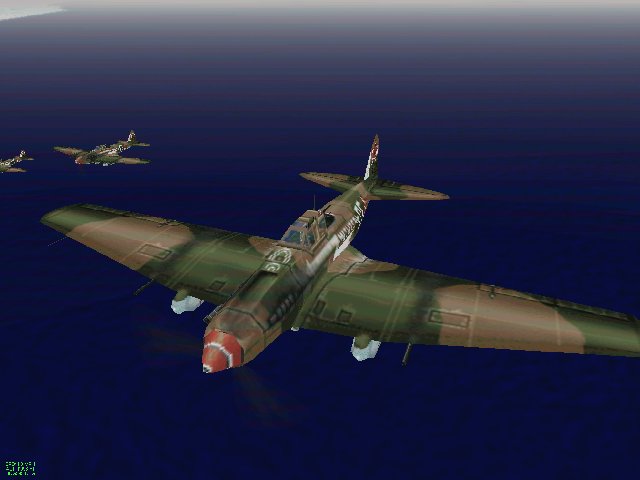
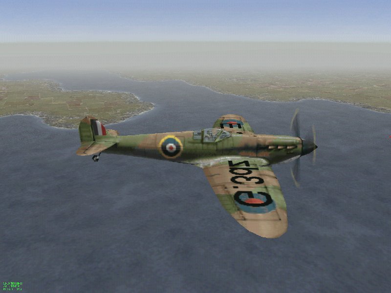
On The Firm's Defiant these paste on items were used to add the turret, the forward radiator, and the retractable aerials on the undersurface of the plane. On Charles Gunst's IL2, the paste-on files were used to form the wing nacelles, and on his Rufe, were used to form the floats.
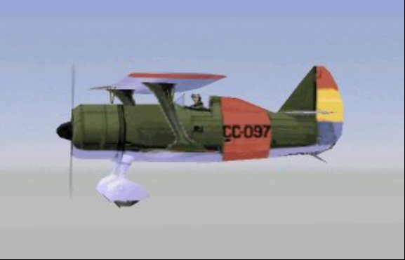
In Captain Kurt's I-15 bis a paste-on file was used to form the upper wing
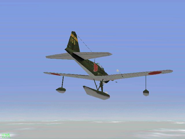
Charles Gunst's Rufe uses paste-on files to make the floats - his IL2 uses paste-on files to form the wing nacelles

The Firm's Invader uses all available stick-on files to create dorsal and ventral turrets, DF loop aerial and the radio masts and wires
The Firm's Defiant uses paste-on files to create the turret, the lower radiator, the lower radio masts and wires, and the radar aerial
(3) New High Resoloution Aircraft Models
One of the applications of using all of the available parts of the EAW aircraft model opened up the prospect of new fighter models using several instead of one, skinfile, and there achieving a high resoloution effect without breaking the 256x256 skinfile limit. I posted this basic illustration of the possibilities in October 2001, showing a spitfire model made not from one 3dz file, but from three 3dz files, and using different skinfiles for the fuselage, the port wing and the starboard wing. To produce completed models would obviously take a great deal of work, but members of the EAW community were up for that.
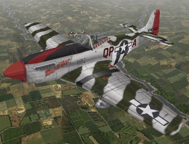
The first fully realised EAW hires model was Chompy's wonderful P51, where A.3dz and B.3dz form the two sides of the tail and rear fuselage, C.3dz forms the cockpit and associated parts of the fuselage, F.3dz forms the forward fuselage, and E.3dz and G.3dz form the port and starnoard wings. Each of these files is able to have its own skinfile, solving all mirroring problems. The onlt limitation is that all transparent elements must use the main TEX skinfile, as within the EAW model, only the main TEX skinfile for any slot can have the transparency enabling TRA file.
Return to RAF Chattenden Moggy's Home Page