

Moggy's Notes
Tardata.dat
Places the individual target ground objects in the airfields and towns
(1) Tardata.dat basic file structure
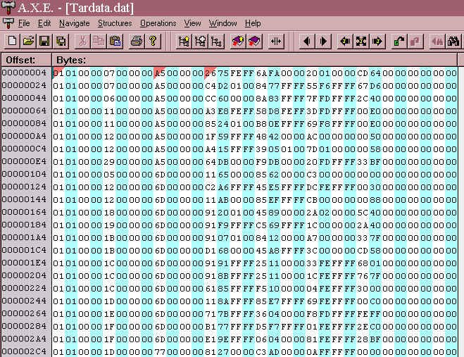
[The first few records of tardata.dat set up in AXE with line length at 32 bytes and starting at byte 4 after the header]
Tardata.dat sets out the airbases and actual target mods at each location with respect to the "marker" placed by targets.dat. Tardata.dat in effect sets up a local version of the EAW grid, and using that grid places the airbase, buildings, AA guns, and other static target objects, and fixes their orientation. See DOM's note's as to the format of the coordinates in this grid system.
As set out in the illustration above, with 3,826 records or lines of 32 bytes each, each record deals with a single scored ground target. This file does not deal with non-target ground objects such as trees, farms, and city buildings etc, which are placed by EAW_ttd.dat.
From the illustration it will be seen that the records are organised in groups with an identical value in the 9th byte - this is the record or line number from targets.dat.
Bytes 0 has values 01, 81, 09 or 89, and byte 1 has values 00 or 01. The function of these are unknown.
Bytes 2-3 are always null.
Byte 4 contains the tmod file number (in hexadecimal format) and therefore identifies the target type. In the illustration above, in the first two records the value at byte 5 is 07, and tmod07_*.3dz is the railhead.
Bytes 6 and 7 are always null
Bytes 8-9 contain the record or line number of the target location from targets.dat.
Bytes 10-11 are always null.
Bytes 12-19 contain the two groups of coordinates for placing the target in the local grid system.
These can vary from 0000 f0ff 0000 f0ff to ffff 0f00 ffff 0f00 and cover quite a large area. Effectively however, as I discovered in making the Dunkirk addon, the useable area is defined by coordinates 0000 f8ff 0000 f8ff to ffff 0700 ffff 0700. Objects placed out side this area are not always there once you enter the game world! This is none the less quite a large area to deal with, as these layout shots from Dunkirk illustrate:
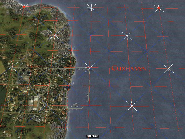
This screenshot shows one quarter of the available "target area" overlaid with a grid illustrating the tardata.dat coordinate system
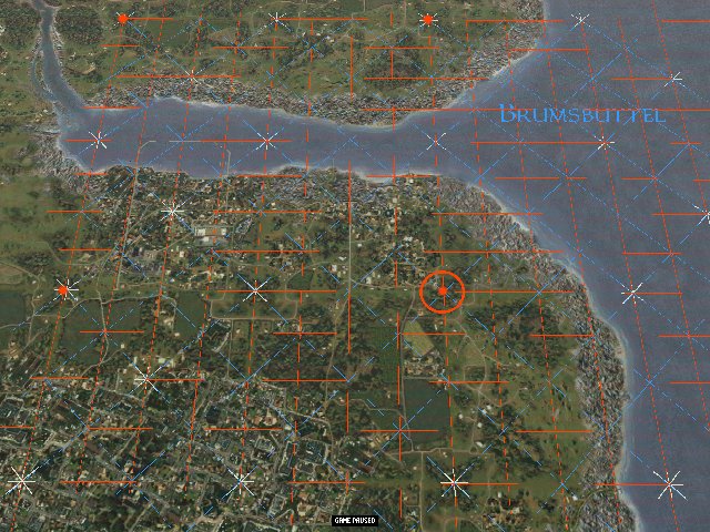
This screenshot shows a greater part of the available target area with the centre of the local coordinate grid marked
The purpose of bytes 20-23 is unknown, but bytes 24-25 set the orientation of the target (except airbases the orientation of which is dealt by airfields.dat) with 00 00 being north, and 0080 being south.
The purpose of bytes 26-27 (many are null) is unknown.
Bytes 28-31 are always null.
In working with tardata.dat you can change the number, type, and position of target objects at any given location. You can add lines to tardata.dat by changing the number of records set in the header bytes. In doing that you may need to change the numbers of targets for each location, and the starting record number for each location which values are stored for each location in targets.dat as explained on the targets.dat page.
(2) Working with the Tardata.dat coordinate system
These coordianates are very similar to the "whole EAW world" coordinates in targets.dat, except the centre is of course the centre of the target location you are dealing with which is fixed in targets.dat.
These coordinates in tardata dat are in the form i.e. 0080 FAFF 0080 FDFF. These are haexadecimal numbers so each coordinate can run from 0 to F. The particular form of number storage used by the EAW programmers means that the sequence of superiority within those number groups like this 3-4-1-2. So "0080" ordinarily expressed would be "8000"
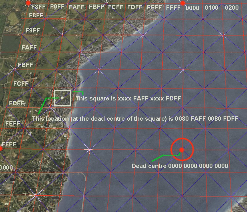
Hopefully this diagram sets out the basic elements. There are four blocks of four numbers which form the coordinate system, as my tardata.dat page sets out. Although others may think about this differently, the way I think about it is that the second and fourth block of numbers set the grid square, and the first and third block of numbers set the position within that square.
The diagram above shows the northwest sector of the target location. The colums go from F8FF farthest east to FFFF in the centre of the location (and continue into the western sector 0000 to 0700). The rows similarly go from F8FF farthest north, to FFFF at the centre of the location (and continue into the southern sector 0000 to 0700).
The highlighted square is therefore at the intersection of colum FAFF and row FDFF, and all tmod locations in that square will have the form as shown xxxx FAFF xxxx FDFF.
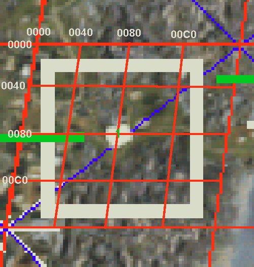
This second diagram shows the small sqaure and how those first and third number groups fix the position within. As you see 0080/0080 is the dead centre of the small square. There are increasingly fine graduations of the coordinates available here. The third coordinate runs across the square from 0 to F, but each of those 16 divisions is dividable into 16 sub divisions set by the fourth coordinate i.e. 0088. The first and second coordinates give excruciating levels of detail that the original programme uses but probably you rarely need.
Return to RAF Chattenden Moggy's Home Page