
Moggy's Notes
Surviving rendering sequence problems
That is without doing severe violence to your computer!
The 3dz Rendering Sequence is undoubtedly the most complicated and infuriating thing you ever tackle in editing EAW 3d models, and pending the new utilities Alessandro Borges is planning, it seems there are no easy shortcuts to significant RS problems. It takes work and patience. I have little of the latter and working with the RS is a chastening experience.
The best explanation I ever had of the way in which the RS actually works, came inevitably from Paulo Morais, and this is it, which I'm sure he won't mind me reproducing:
"The base idea of the BSP trees in EAW context is to subdivide the space around the model in cells. The walls of the cells are made of infinite planes that are coincident with the polygons that make the model. Ex: one of the vertical tail elements (doesn't matter which one) of an aircraft can be used to define a plane that slices the entire model in two. Now lets say that this element is the one that is visible when looking from the left. You may say that half of the remaining model elements are above(or in front) when they rest to the left of it and the others are below (or to the back) of it. Next you can choose one of the two new groups and select one the elements in the selected group to slice the group in two. Repeat until you end with individual elements. The final result can be compared with a tree with the first slicing element as the root. The end of each branch only contains empty space. EAW represents the tree by a sequence of pairs of numbers, the so called rendering sequence table. The number of pairs stored is the same as the number of elements plus one (the starting pair). This pair is the first one in the table and for this we should give it a special name (ISTR). ISTR points to the first slicing element by referencing is number inside the file. The second number of the pair is arbitrary (its unused in this pair). I will present a arbitrary example:
ISTR 3 0
I000 2 255
I001 255 255
I002 255 1
I003 0 255
The first column was added to address each pair. Inside a 3DZ you will only find the numbers to the right sequentially. Lets start reading the table:
ISTR says element 3 is the first slicer of model space. You must go to I003.
I003 says element 0 is above me; no element is below me (255 is a end of sequence, same as empty space). Go I000.
I000 says element 2 is above me; no element below. Go I002.
I002 says no element above me; element 1 is below. Go I001.
I001 says no one is above or below me. End of sequence.
The above is a very simple BSP tree. You can have elements with above and below elements at the same time. You can see them as a branching point in a tree. Anyway, this doesn't matter, all is the same as before. The only problem is that you need to track down more sequences at the same time. Now things are starting to get ugly. You must find how your misplaced elements relates with is neighbours both in terms of 3D and in terms of BSP tree and create if possible a mental image of it. I am not joking, with a lot of practice you can start to get the hang of it and start predicting which are the slicing elements by simply looking into the 3D model. Now a set of rules or normal causes of problems. Elements can't be sliced for real by the current slicing plane. All elements that remain to be classified (or placed in the BSP tree) must be entirely to left, or to the right of it. Another possibility is for a element to share the same slicing plane. In that case you get the compound elements like stoped, animated, old-style line propellor blades. Elements must be flat. If due to editing a element with more than three nodes gets non-flat it will intercept its own slicing plane. In those cases the only solution is to break the element into smaller flat pieces and find the right places in the BSP tree for all of them. Almost forgot the mathematical definition of the slicing planes for each element is stored in what is called the normals section. The data there contains the 4 constants that define a plane in space (plus a object identifier). The three normal vector components and a offset term.
Ax + By + Cz + D = 0
where A B C are the normal vector components and D is the offset.
By replacing the coordinates of a point into the above equation you can get 0 for a inplane point, a positive number for a point 'above' the plane and a negative number for a point below. The absolute value gives a measure of the distance to the plane. By testing all the nodes of a given polygon with above equation for the current slicing plane you can mathematically determine if it is above, below, crossing(bad) or in the same plane."
Now I can't say I understood all of that, I have no training in computers, and even less in computer 3d graphics, but Paulo's example gave me a rough sort of mental picture of how the thing worked, and in dealing with the RS problems I had - I thought the best way to proceed was to draw out the whole BSP tree, and see where each group of elements was in relation to the rest - if the RS was displaying the wrong element in front, I needed to know where both elements were in the overall scheme in order to see if there was anything I could do about it.
So this is "The Invader Story ..."
The important thing I got from Paulo's explanation, and particularly from Paulo's small example tree, is that if you look at the rendering sequence in the 3dz file, it is arranged as follows: two bytes for the "root" and then two bytes for each element. Each of those bytes has two purposes (1) it contains the element number being rendered at that position, and (2) it refers you to the next position(s) in the RS table. The relative position of the numbers lets you know which element is in front and which behind. The 255 terminators tell you there are no more elements in that position, and the double 255 says no more elements in front or behind therefore the end of a branch.
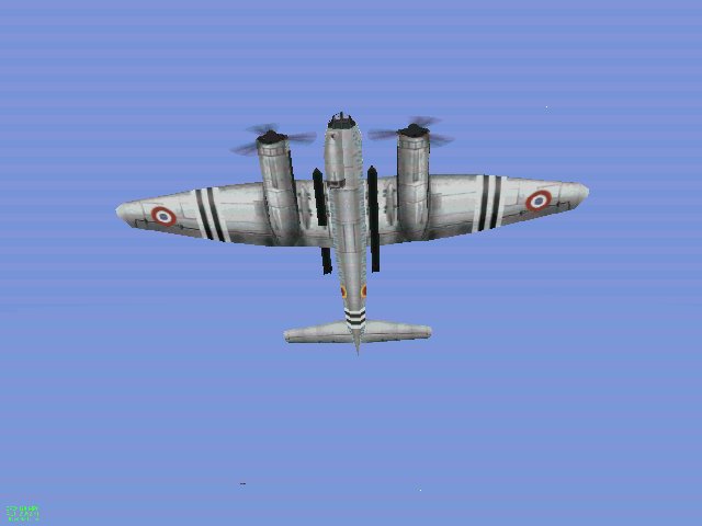
The problem with the invader is clear in this picture:
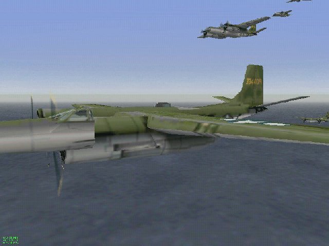
Editing the Invader caused a major glitch in a basic part of the rendering sequence
It resulted from pulling the engine nacelles in the original B26 wireframe, rather dramatically forward to get the characteristic Invader shape. I thought the best thing to do to make it clearer was to take the RS section from the converter dump and see if I could write out the whole BSP tree for the invader F.3dz file. Now in the converter dump the sequence looks like this .....
[SEQUENCE]
;S000= code endcode
S000= 52 0 255
S001= 19 255
S002= 6 16 4 255
S003= 2 7 255 255
S004= 57 255
S005= 53 255 255 255
S006= 5 255
S007= 10 255
S008= 11 255
S009= 30 13 3 195 255
S010= 56 155 255
etc etc ...
[END]
...but like this it isn't the most helpful form for my purpose. I thought it would be more useful if it could be seen in the form it actually appears in the 3dz file, i.e. with the root and two bytes for each element. So I got rid of the S numbers, and put in a new "position number" for each two byte section and keeping the correct sequence of element numbers and 255 terminators, I got this:
[MOGGY'S REFORMATTED SEQUENCE]
ROOT: 52 0
000: 255 19
001: 255 6
002: 16 4
003: 255 2
004: 7 255
005: 255 57
006: 255 53
007: 255 255
008: 255 5
009: 255 10
010: 255 11
011: 255 30
012: 13 3
013: 195 255
014: 56 155
015: 255 28 etc etc ...
Here, the first two byte section is the root (actually the tail fin) and the table proper starts with section 000 as in Paulo's small example. You can now follow the sequence as in Paulo's note: the root is element 52. You forget the "0" in the root, which is just a placeholder. The root means element 52 is drawn first, and it begins the sequence by referencing position 52. At position 52 we have element 58, so element 58 is drawn next, and it references position 58. At position 58 we have element 59, so element 59 is drawn next, and it references position 59 ... and so on. Note that at this stage each position contains one element number and a 255 terminator, so we are going straight up the tree from the root with no branches developing. Note also the relative position of the element number and the 255 terminator is telling us whether the next element to be drawn is behind or in front
Following the tree as above we finally get to position 14. This contains two element numbers and no 255 terminator, so here we have the first branching to positions 56 and 155, and each of them continues the sequence separately. Sooner or later in every branch you get to a position which contains two 255 terminators - no more elements in front or behind, and that is the end of the branch.
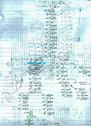
Here's a scan of part of the tree as I drew it up for the first time - sorry this is a typical Moggy "back of an envelope" job.
Moggy's sophisticated analysis techniques :)
At the top you can see the root 52, and the main stem following the sequence down to position 14 where the first branching takes place. Ignore the parallel column in pencil, those are the numbers for the G.3dz file.
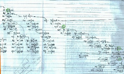
This scan of the tree shows you my problem. The cockpit and associated fuselage elements doing the overlapping are those circled in green further down - 6, 8 ,19, 17, 18 and 20. The engine nacelle elements are on the other branch starting with 63. If you look at the second scan you can see that the other engine nacelle elements being overlapped 69, 68, 67, and 71 follow down the other branch. As Paulo spotted, the engine face 63 is right at the split of a significant branch and system of branches of the tree. Moving the elements did not seem to be a realistic proposition. It would involve an enormous amount of work, and essentially rewriting a major section of the tree. That was certainly beyond what I could do. However, it did occur to me that there might be another, if less elegant solution.What if the engine nacelle elements were copied and those copies treated essentially as new elements?
(1) they could be rendered on screen for a second time (in exactly the same place) so that they were not overlapped by the cockpit/fuselage elements,
(2) the original nacelle elements could be left in their original place, and no disruption to that part of the tree would be caused
This is what I did. I copied the elements 63, 67, 68, 69, and 71 and made "new" elements 200-204. These were added to the element table in the converter dump. However, in order to do the job properly it was necessary to do the same thing with the prop and spinner elements 130-35, 175-80, 164 and 126-129 which were also being overlapped, so I created "new" (=copied) elements for those as well. Having created these "new" elements, I adjusted the number of elements at the head of the converter file, and also copied the normal sections using the new element numbers.
The next part is the trickiest - finding the right place in the BSP tree to insert these new elements. As the highest (= nearest the root) element causing the problem was 6, I chose to insert the new elements at the position above that. If you look at the first scan of the tree you see that the position above element 6 is position 129, which contains element 1 and a 255 terminator. I then looked for element 1 in the original converter RS dump:
S076= 187 255 255
S077= 127 255
S078= 128 255
S079= 164 1 255
S080= 132 255
S081= 133 126 134 255
S082= 135 255
and it was at converter line S079. I replaced element 1 in the converter dump with the first new element 200 as follows:
S076= 187 255 255
S077= 127 255
S078= 128 255
S079= 164 200 255
S080= 132 255
S081= 133 126 134 255
S082= 135 255
That new element then references a new position - 200 which does not yet exist. Remember you have to have the same number of positions in the sequence (plus the root) as you have elements. This is clearer if you look at it from the point of view of my reformatted sequence table. Position 129 now contains element 200. So it renders that element and then references position 200 which must now be created right at the end of the sequence.
[MOGGY'S REFORMATTED SEQUENCE]
ROOT: 52 0
000: 255 19
001: 255 6
002: 16 4
126: 255 127
127: 255 128
128: 255 164
129: 200 255
130: 132 255
131: 133 126
132: 134 255
197: 23 255
198: 140 255
199: 79 255
200: ...........
[END]
To accommodate all the new elements a chain of new positions is created. Position 200 renders element 201 and references position 201, position 201 renders element 202 and references position 202 and so on ..... and in the original converter format they look like this, tacked on the end of the sequence.
[SEQUENCE]
;S000= code endcode
S000= 52 0 255
S001= 19 255
S002= 6 16 4 255
etc
S125= 201 255
S126= 202 255
S127= 203 255
S128= 204 255
S129= 205 255
S130= 206 255
S131= 207 255
S132= 208 255
S133= 209 255
S134= 210 255
S135= 211 255
S136= 212 255
S137= 213 255
S138= 214 255
S139= 215 255
S140= 216 255
S141= 217 255
S142= 218 255
S143= 219 255
S144= 220 255
S145= 221 255
S146= 222 255
S147= 223 255
S148= 1
[END]
The final line here refers the sequence back to element 1, so the sequence can continue where it left off.
I had to experiment with the final line. By my reckoning it ought to be the same as the original "1 255" I displaced, and that's what I put in and indeed when I converted the file it worked to my great pleasure and not a little surprise. However, when I converted the file back to text for further work, the final line was as shown, and it might be I had one too many 255's! Well there it is. More bodge than anything else, but the advantage is that it worked!
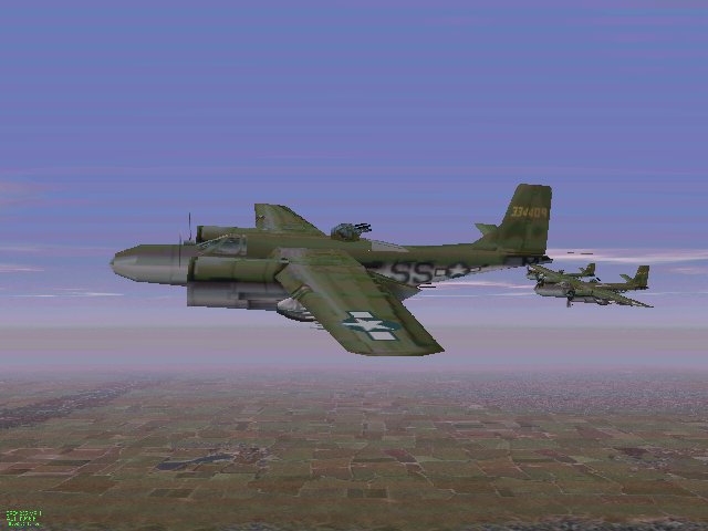
Duplicating the engine nacelle and associated elements elsewhere in the sequence solved the problem
I have subsequently used this method of duplicating overwritten elements in anumber of planes including the Defiant, and the Halifax. One problem in particular that it has been helpful in solving is the situation which arises when weapons station hardpoints are installed on a plane which has not previously had hardpoints, and there are rendering problems when the visible ordnance extends across several wing elements. The ordnance may show against some elements but not others. The ordnance may show through the wing and be visible from above.
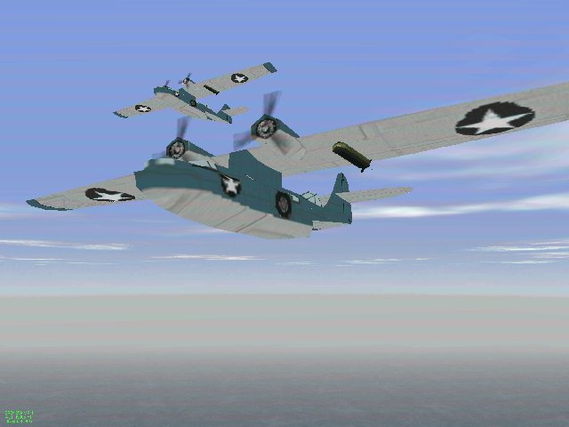
The Firm's Free French Ju88 shows the ordnance rendering problem - the Midway PBY shows the problem solved
I first had the former problem in putting the jury rigged torpedo on the Midway PBY. It was solved by duplicating the wing element carrying the hardpoint at a superior point in the sequence. The element was being drawn two or sometimes three times (in effect different parts of the ordnance were being drawn with each duplication) but this extra claim on system resources is nothing to modern systems or video cards, and the player will only see a properly drawn element.
Return to RAF Chattenden Moggy's Home Page